PCB Buyer’s Guide
Choosing the right printed circuit board (PCB) material requires finding a balance between numerous factors, including production volume, cost and design demand. In this printed circuit board guide, we’ll equip you with the knowledge you need to buy the right PCB for your project. You’ll learn what a PCB is, which types are available, how to buy one and more.
What Is a Printed Circuit Board?
Printed circuit boards are the basic building blocks of almost all electronic devices today. This includes machines as simple as single-layer boards in garage door openers and as complex as the 60-layer high-speed and high-density circuit boards in servers and supercomputers. PCBs are the foundations on which all other electronic parts are assembled.
Components like connectors, semiconductors, diodes, resistors, radio devices and capacitors are all mounted to — and communicate with each other through — the PCB.
PCBs have electrical and mechanical attributes that make them perfect for certain applications. Most PCBs made worldwide are rigid boards, and the remaining ones are more flexible, allowing circuits to be folded into shape. Sometimes flexible PCBs are used in situations where their malleability enables them to endure hundreds of thousands of flex cycles without breaks in the circuits.
A tiny subset of flexible circuits is known as rigid-flex circuits. Certain portions of their boards are rigid, which is perfect for attaching parts, and other sections are flexible, providing the benefits of flexible circuits.
There is also a quickly emerging technology, different from the ones above, known as printed electronics. Printed electronics are usually low-cost, simple circuits that lower the expense of electronic packaging to the level where electronic solutions can be created for problems never before thought of. These are frequently used for disposable electronic devices or wearable applications and open many opportunities for imaginative electrical designers.
Traditional printed circuit boards range from extremely simple to complex. They are comprised of electrical parts and connectors linked with conductive circuits that usually consist of copper and route electrical power and signals between and within devices.
PCBs were first developed in the early 1900s and have improved dramatically ever since. The advancement and wide adoption of PCB technology have paralleled the fast improvements in semiconductor packaging technology, enabling the industry to invest in smaller, more efficient electronics.
What Is a Printed Circuit Board Used For?
PCBs are used in devices in a wide range of industries. Some of their most common applications include:
- Medical devices: Medical machines that use PCBs include monitors, CAT scanners, internal devices and infusion pumps.
- Consumer electronics: Computers, smartphones, home appliances and many other consumer products require PCBs to work.
- Industrial equipment: Numerous power, measuring and manufacturing tools have PCBs.
- LEDs: Light-emitting diodes, which are found in computer displays, automotive displays, medical lighting and residential lighting, all use PCBs.
- Automotive components: These days, printed circuit boards are in car parts such as control systems, navigation systems and sensors.
- Aerospace components: Communication tools, monitoring tools and power supplies in the aerospace industry use PCBs.
- Security equipment: PCBs are found in security and safety devices such as smoke detectors, security cameras and electronic door locks.
Types of Printed Circuit Boards
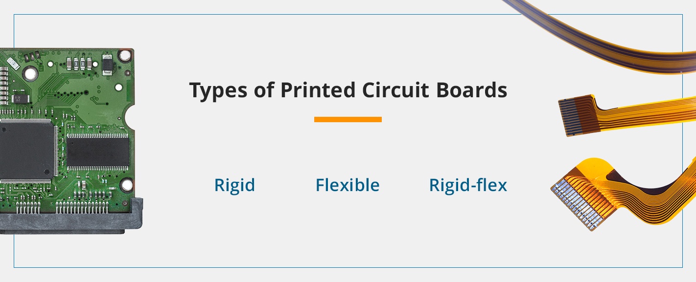
Although all printed circuit boards serve the same basic purpose, they come in a wide array of configurations and designs to suit different applications. The three most common types are:
- Rigid: A rigid PCB consists of rigid fiberglass substrates, which makes them affordable and practical — but also inflexible. They’re cheaper and easier to manufacture than the more flexible PCBs but considerably less versatile and difficult to fit in places that are small or have uncommon geometries.
- Flexible: Flexible printed circuit boards have fairly good folding and bending capabilities to fit into unusually shaped or small spaces. This capability makes them versatile and allows them to be used to package smaller electronic devices. Furthermore, because they’re adaptable, the product doesn’t need to be constructed to fit around the PCB’s restrictions. Flexible PCBs are often more heat-resistant than their rigid counterparts.
- Rigid-flex: Rigid-flex printed circuit boards combine the best qualities of both flexible and rigid PCBs. Unlike rigid and flexible models, rigid-flex printed circuit boards have their electronic interconnectivity buried in the board, which reduces its overall size and weight. They’re a good choice when extra-light packaging is required. They’re also more reliable and durable while retaining flexibility and great strength.
Printed Circuit Board Components Guide
Printed circuit boards come with various parts that enable them to carry out their work. The printed circuit board components you’ll usually encounter include the following types of PCB hardware.
Supports
Types of supports include edge locking, adhesive base, screw locking, reverse locking and snap lock. You can fix them in various ways, including locking arrowhead, fir tree mount, quarter-turn, flat rest and locking bayonet.
As for the material, supports are available in nylon, acetal and ethylene propylene diene monomer rubber (EPDM). They allow for operating temperatures from minus 40 degrees Fahrenheit to 185 degrees Fahrenheit.
Spacers and Standoffs
Spacers and standoffs are perfect for consumer electronics and data cabinets.
Standoffs and spacers come in many different lengths and internal diameter options, which will ensure the correct position for the application. Standoffs are available in female-female, female-male and male-male variants.
There are also many bodies available, which will allow for numerous tightening possibilities. These bodies include round standoff, hexagonal standoff and round with crossed body.
As for materials, spacers can be either PCB plastic or ceramic. Standoffs are available in three materials — glass-filled nylon, nylon PCB standoffs and nylon with brass inserts.
Choosing the most suitable spacing component can be challenging, and the material and application are important considerations. However, the most critical factor is perhaps the mounting type. We’ll provide some examples below:
- Threaded: The threaded mounting types available are the standard, which is held in place with a nut, and the undercut, which provides a better connection by being fixed into the thread. There is also self-tapping, which requires no nuts or closing washers.
- Snap fit: This mounting type pushes quickly into a chassis hole or panel, providing strong, efficient mounting that will save you time during the installation. The kinds available are bayonet, fir tree and edge lock.
- Snap lock: This mounting type pushes into a chassis hole or panel, providing an easily releasable but secure fix.
- Press fit or blind hole: With this mounting type, fins securely hold to numerous bind holes. Its painted style easily drives into applications with space restrictions.
- Adhesive base: This type features an adhesive tape, which provides space and time efficiencies by eliminating the need for mounting holes.
Card Guides
Card guides will ensure your circuitry is completely accessible. Several mounting methods are available, including snap-in, screw, push-fit and adhesive, which offer a removable or semi-permanent locking function. They also come in many materials, including stainless steel, acetal, polystyrene, polycarbonate, nylon, acrylonitrile butadiene styrene (ABS) and polyvinyl chloride (PVC). They provide operating temperatures from minus 40 degrees to 284 degrees.
LED Hardware
Some LED products used in PCBs include LED lens holders, light mounts and spacers. LED mounts can be easily snapped in and allow users to mount LEDs at a 90-degree angle. LED spacers provide users with wire retention and height control with various LED types, made to fit the printed circuit board you’re using.
PCB Design
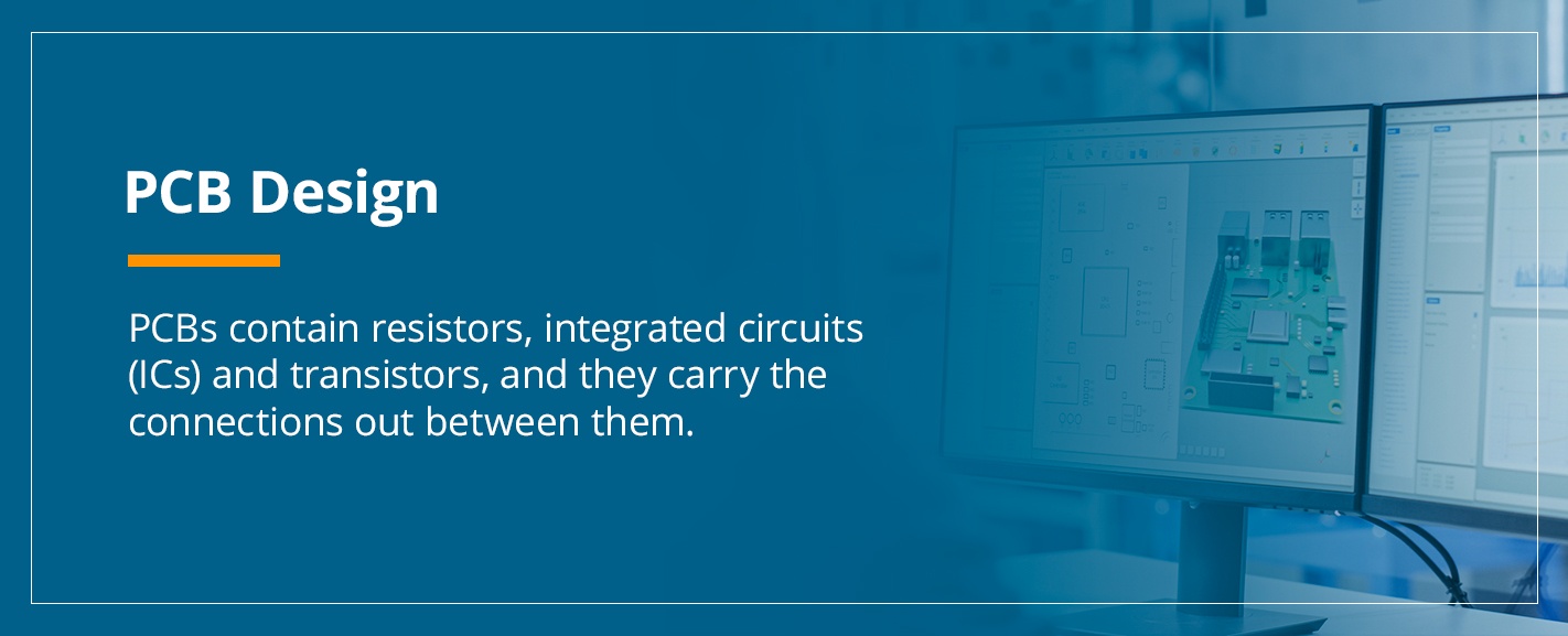
PCBs contain resistors, integrated circuits (ICs) and transistors, and they carry the connections out between them. Printed circuit boards let users route signals and power between multiple physical devices.
Solder joins those boards and small parts together. This miraculous metal makes electrical connections and acts as a powerful mechanical adhesive. Think of PCBs as lasagna slices — the ricotta cheese and sauce is the soldering, and the layers of noodles are the boards.
As you already know, PCBs play important roles in the modern world, so whoever brings your design to life must have a robust program. This point is particularly true if you have a complex layout.
Eagle vs. Altium
Eagle and Altium are two common PCB layout design programs, and conversations comparing the two are common between board suppliers and electronic companies. Buyers tend to prefer Eagle, which is generally free, whereas electronic design manufacturers usually prefer Altium.
However, free software has limitations. For instance, whereas Altium places no limit on how many layers users can design in, Eagle has a limit of four. Altium also places no limit on a design’s size, whereas Eagle limits them to 160 square centimeters.
If you want to design exactly what you desire with no limitations, it makes more sense to pay for a high-quality suite of tools.
The Designing Process
When dealing with an experienced vendor, you can expect the design process to go more or less as follows if you’re outsourcing services:
- You approach the vendor: You present a design idea to a vendor. The vendor’s engineering group meets with your design team to learn how you’d like the product to function. How much time this takes will depend on the components’ complexity and the amount of back and forth involved in optimizing the design.
- The supplier creates a schematic: You will review the supplier’s schematic. As schematics ultimately control your project, you must take this step to determine whether the vendor is thorough and accurate.
- The PCB is designed: Opening the schematic with Altium or another PCB layout program, your designer will create the PCB.
- The circuit board is generated: Once you okay the board, your designer will develop a Gerber file, which they’ll use to generate the bare circuit board.
- The board is assembled: The board goes through the assembly process, where the tiny components are carefully placed on the PCB.
- Quality inspections occur: How intense these inspections are depends on your product industry and application.
Tips for Buying a Printed Circuit Board
In this section, we’ll provide some tips for purchasing a PCB batch for an electronics project:
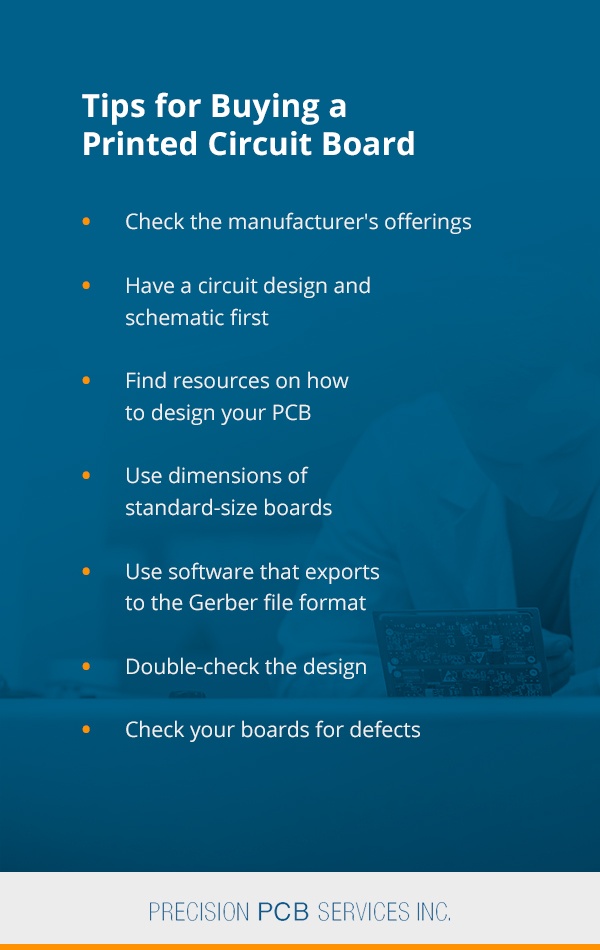
- Check the manufacturer’s offerings: Before ordering the boards, see if the manufacturer you’re considering offers short runs or standard sizes. Doing this will allow you to purchase a cheap set and avoid paying for a big batch of custom boards when you need only a small number.
- Have a circuit design and schematic first: You won’t need a circuit board if you don’t even have a circuit first. Use available software tools to create a schematic. The platform should ideally let you simulate and test the circuit’s behavior and make a minimum of one functioning project prototype to make sure it’ll work before you order your boards. If the circuit doesn’t work, it won’t matter how high-quality your board is.
- Find resources on how to design your PCB: Once your schematic and prototypes have been tested, it’s time to produce your PCB. Many manufacturers provide their own solutions for designing boards. We recommend you take advantage of these resources for an easier and more efficient process.
- Use dimensions of standard-size boards: Since you’ll probably order a standard-size board, you should set the project for the design using those dimensions. Otherwise, the manufacturer might be unable to build it at the specified price, since they’ll probably think of it as a custom job.
- Use software that exports to the Gerber file format: Using software to design your boards has many benefits, although one of the greatest is that output files have become standardized. They all use the Gerber format, which is what the plotters use when they print the tracks on your boards. Whatever software you use, make sure it can export to this format.
- Double-check the design: Look carefully over your design, prototype and board layout, because if you don’t discover a mistake until after the boards are ordered, this will require replacements. Replacements will cost you more time and money. Therefore, make sure everything is right. Once you’ve done that, choose the boards you’d like to order, upload your Gerber file and make your purchase.
- Check your boards for defects: Once your PCBs have been delivered to you, check them closely for shipping damage and manufacturing defects. These can include holes left undrilled, broken boards and defective or incomplete tracks. By doing this before beginning the soldering process, you’ll be able to quickly have a replacement ready in case of a defect.
Check Out PCB Services and Training Classes From Precision PCB Services
Precision PCB Services offers a full line of cutting-edge PCB repair and rework services to help contract manufacturers, product researchers and developers. We specialize in fast turnaround times to help you get your product to market in a timely fashion.
We also offer soldering training and certification classes, which are taught in adherence to IPC soldering guidelines.
Some of our most common PCB repairs and rework projects are:
- Ball grid array (BGA) reballing.
- Installation and removal of plated through-hole (PHT) and surface mount components.
- PCB repair.
- Trace repair.
- Laminate repair.
- Surface mount pad repair.
- Gold finger contact repair.
- BGA components rework.
- Solder mask repair.
- Inner layer repairs.
For a quote for our PCB services, reach out to us using our contact form. We look forward to hearing from you soon!